Descrizione
Planetary Sun Gear – Custom Precision Central Gear
Custom sun gears for planetary stages where concentricity, tooth accuracy and the input-side interface directly influence load distribution across every planet gear.
What This Product Covers
This page is written for engineers and sourcing teams working with sun-gear concentricity, tooth geometry and input interface control. The product is not presented as a universal off-the-shelf substitute for every planetary transmission. Instead, EVER POWER treats the assembly as a geometry-controlled system. That distinction matters because a planetary stage shares torque through several simultaneous meshes; a component can look correct on the bench and still generate uneven load, edge contact, noise or premature wear if its mating geometry or datums do not match the surrounding members.
Typical enquiries involve servo reducers, industrial planetary drives, wheel and track transmissions, slewing systems and compact high-torque gearboxes. For these projects, the first task is to identify what information is authoritative: an original drawing, a serviceable sample, a complete mating set, a verified gearbox model, or measured data from an existing assembly. We then separate dimensions that are directly confirmed from values that still need engineering confirmation. This evidence-first approach helps prevent the common mistake of turning a family resemblance into an unsupported interchangeability claim.
Browse Planetary Gear Products
Functional Role Inside the Planetary Stage
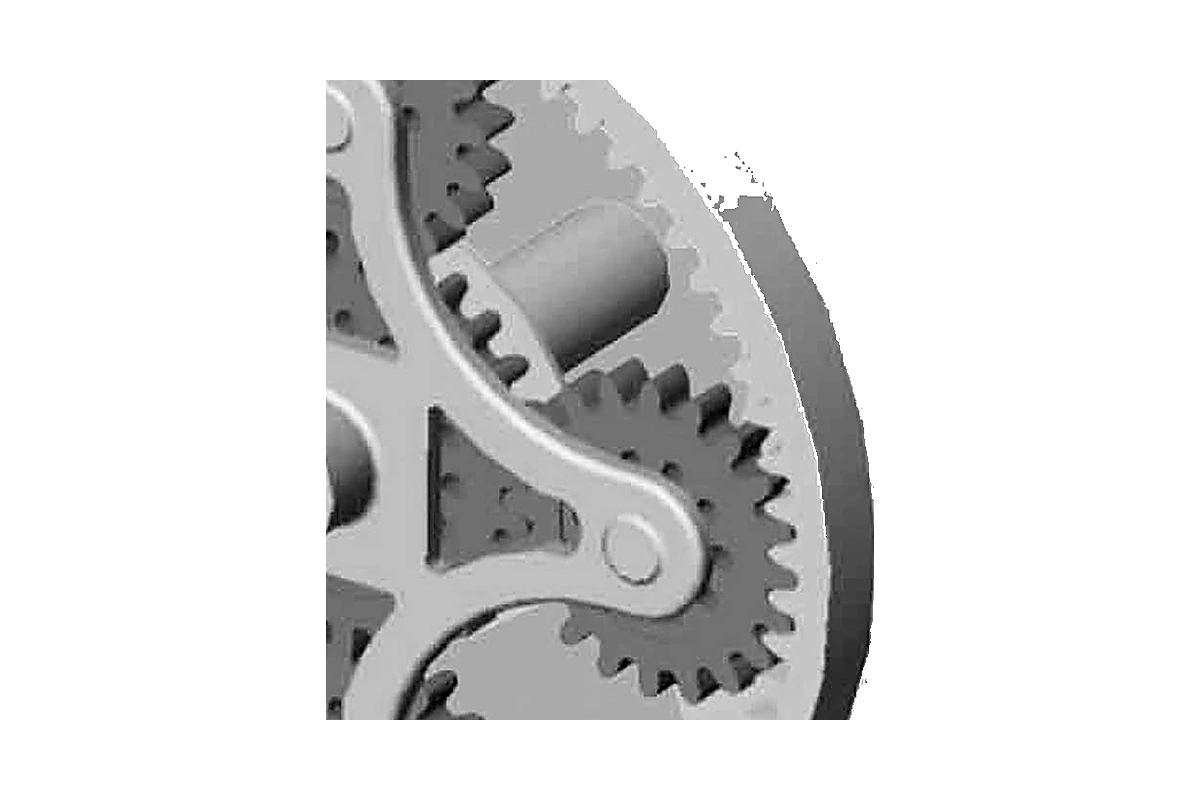
In a conventional planetary stage, the sun gear, planet gears, internal ring gear and carrier form one kinematic system. Depending on which member is driven, held or used as the output, the same basic architecture can provide reduction, speed increase or differential motion. For planetary sun gear – custom precision central gear, the practical purchasing question is therefore not only whether the tooth count is correct; it is whether the member will run on the intended centers, carry the expected load through the designed contact area, and maintain the required relationship to bearings, splines, pins and housing datums.
A replacement sun gear should be specified from the original drawing, a verified sample or complete mating-gear data. Tooth count by itself is insufficient because profile, pressure angle, helix, tooth thickness, datum relationship and shaft connection determine whether the mesh will actually run. During review, we also distinguish nominal operating torque from transient events such as starts, emergency stops, reversals or shock loads. These events affect tooth-root stress, contact stress, carrier and pin loading, spline interfaces and bearing reactions. When the source package does not contain enough data to validate a numeric limit, the missing field is kept as an RFQ confirmation item rather than being guessed from a similar gearbox.
Information We Need for a Reliable Quote
A useful RFQ lets manufacturing engineering reproduce the functional relationships of the existing stage. The following fields are deliberately broader than a simple tooth-count list because planetary gearing is sensitive to compound tolerances and mating conditions. If only a sample is available, include photographs of both faces, the bore or spline, the mating members and the assembly orientation before disassembly whenever possible.
| RFQ field | What to provide | Why it matters |
|---|---|---|
| Gear geometry | Module or diametral pitch, tooth counts, pressure angle, spur/helical form, helix angle/hand if applicable | Defines mating tooth geometry and basic ratio relationships. |
| Accuracy requirement | Drawing tolerance or required ISO/DIN/AGMA quality level, runout and tooth-thickness requirements | Prevents a high-precision member from being paired with an unsuitable mating member. |
| Interfaces | Bore, keyway, spline, shaft, flange, pilot, pin, bearing seat and datum information | Controls fit to the shaft, carrier, housing and adjacent components. |
| Material & heat treatment | Specified grade, carburizing/induction/nitriding requirement, hardness or case-depth requirement when controlled by drawing | Determines whether the manufacturing route matches the intended load and wear regime. |
| Operating duty | Input speed, output torque, peak torque, starts/hour, reversing, duty cycle, temperature, lubrication and expected life | Lets the gear geometry and material route be checked against real service conditions. |
| Evidence | Original drawing, sample, mating gear data, inspection report or complete gearbox model | Reduces the risk of copying only visible dimensions while missing functional geometry. |
Manufacturing Route: Controlled by Drawing and Duty
The manufacturing route is selected after geometry and service requirements are known. Depending on the component, this may include forging or bar preparation, turning of reference datums, hobbing or shaping, broaching or spline cutting, heat treatment, hard finishing, tooth grinding, honing, internal gear shaping or grinding, precision boring and final inspection. These processes are not claimed as mandatory for every part. The route should reflect the drawing, material, hardness, gear quality and economic batch size rather than a one-size-fits-all recipe.
For replacement programs, datum strategy deserves the same attention as tooth quality. A gear may measure correctly across teeth yet fail in service if the bore, pilot, spline, carrier pin circle or flange is not concentric to the pitch geometry. Inspection planning should therefore connect the functional datum to runout, pitch error, profile/lead measurements and interface dimensions. When a customer provides an old sample with measurable wear, we document the wear condition so that the manufactured geometry is not simply a copy of the worn state.
Material and heat-treatment confirmation
Material selection is handled as a controlled engineering input. If the drawing calls for a defined alloy and heat-treatment condition, that requirement governs. If the original specification is unknown, service information is used to propose options for customer approval. Case-hardened steels, through-hardened steels, nitrided steels and other routes can behave very differently in tooth-root fatigue, pitting resistance, distortion and machinability, so substitutions should never be made only because two grades have similar tensile-strength values.
Mesh Quality, Load Sharing and Noise
Planetary stages are especially sensitive to load sharing because several planets are intended to carry torque at the same time. Manufacturing scatter in tooth thickness, pitch, runout, carrier pin position or bearing clearance can cause one planet to enter contact earlier and take more load. A robust inspection plan therefore looks beyond a single gear. Where possible, the complete mating set should be checked for contact distribution, backlash consistency and free rotation under controlled assembly conditions.
Noise is another system-level outcome. Tooth microgeometry, profile and lead accuracy, surface finish, housing stiffness, bearing condition, lubrication and torsional excitation from the motor or driven machine all interact. A new gear cannot compensate for a damaged bearing seat or distorted carrier. For troubleshooting projects, supply photos of the wear pattern and any available vibration or oil-debris observations; they help distinguish a tooth-manufacturing issue from alignment, lubrication or structural causes.
Inspection Points Before Shipment
- Identity: drawing revision, part number, material and heat-treatment route are matched to the approved order package.
- Tooth geometry: the required module/DP, tooth count, pressure angle, helix data and quality characteristics are verified using the method appropriate to the drawing.
- Datums and interfaces: bores, splines, keyways, pin holes, pilots, flanges and bearing seats are checked from the functional datums.
- Heat-treatment condition: hardness or case requirements are checked when specified, and distortion-sensitive dimensions are verified after final finishing.
- Set compatibility: when supplied as a matched set, mating relationships and identification are kept together so parts from different revision states are not mixed.
- Packaging: finished tooth surfaces and precision interfaces are protected from impact, contamination and corrosion during shipment.
Application Review and Selection Logic
Selection begins with required output behavior, not with an attractive catalogue ratio. Record the motor or hydraulic input, input speed range, required output speed, continuous and peak output torque, duty cycle, starts and reversals, external radial or axial loads, mounting position, lubrication method, temperature and available envelope. This data allows the reduction stage, materials and interfaces to be reviewed against actual service. If the unit forms part of a safety-critical lifting or personnel-protection function, the complete machine safety analysis remains the responsibility of the system designer and the applicable regulations.
For a replacement stage, also record why the old gear set is being replaced. Uniform pitting after a long service interval calls for a different investigation from a broken tooth after an overload, polished edge contact, carrier-pin fretting or recurring spline wear. Root-cause information can change the proposed manufacturing or assembly checks. When the reason for failure is unknown, the safest approach is to preserve the original design evidence and ask for the operating history rather than silently modifying geometry.
Related Planetary Gear Components
A planetary stage is normally quoted more reliably when mating components are reviewed together. If the current project involves a complete stage rather than one isolated replacement member, provide the associated drawings so tooth and datum relationships can be checked at the same time.
Request a Technical Review
Send the drawing package, quantity and operating duty to [email protected]. EVER POWER can review the available evidence, identify the fields that are still missing, and prepare a manufacturing quotation without filling gaps with invented dimensions. For reverse-engineering enquiries, include the condition of the sample and whether the mating gears are available for inspection.